|
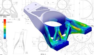
Finite element analysis (FEA) is a software tool engineers use to simulate and analyze the performance and stresses associated with a design. In the past, only larger companies had the software, hardware, and experienced people needed to take advantage of FEA.
Today, sophisticated analysis and simulation tools are within reach of even the smallest companies. How can your company benefit from FEA? You’ll get better designs and lower costs. With FEA, engineers can simulate machines, products, and processes to determine weaknesses and make corrections before prototyping or testing.
How to get started? If you are not already using FEA to improve your engineering projects, you should consider how your company could cut costs and enhance your engineering results. Almost all CAD packages have an option for some FEA features. If it is not something your company is ready to do internally, or you don’t have the time, reach out to Lee Engineering. We have the latest FEA software, other design tools, and decades of engineering, manufacturing, and design experience to help you with your FEA requirements and make your designs the best they can be. Contact us to get support on your next project! By Richard Lee – Lee Engineering Inc.
Is it human nature to add complexity when solving problems? Whether engaged in the design, engineering, cooking, government, management, staffing a department, programming, or even writing sentences, we tend to add features and complexity. Sometimes "more" becomes the root cause of many problems later. To make matters worse, we often add rather than subtract when fixing new situations! It can become an endless cycle. A band-aid on top of a band-aid. Over-engineering. The add-more approach often increases costs, waste, complexity, bureaucracy, maintenance, and lead time slows productivity, and may be more prone to failure. Adding is frequently not the best strategy. It may be the worst approach to solving some problems. Still, adding complexity is the most used strategy. Many overlook that option even when a better method is to subtract and simplify. Why do people tend to add rather than subtract? Does adding to a design or process create a visible legacy? Is it a monument to our hard work and creativity? Have you ever looked at a Rube Goldberg contraption while someone else comments, not sarcastically, about the ingenuity that must have gone into it? Ironically, finding a simple solution for a problem or design can be the most challenging approach, but it always looks easy in hindsight. When done well, there is little evidence of the hard work involved! In my experience, making something simple and elegant takes much more thought up front and a few more design iterations. Sometimes subtracting and simplifying goes against popular opinion. You may be tearing down someone else's legacy or contributions if you find ways to take an existing machine, product, or process and make it better by removing parts, features, or steps. If you propose eliminating an "ingenious" Rube Goldberg legacy contraption, protests and obfuscation by the originator may occur. Ultimately, the added effort of creating a simple solution is usually worth it. However, when looking at the simple solution, few people will ever know that the first draft was a more complex, "ingenious" Rube Goldberg solution. It turns out that researchers have studied why we use adding complexity as the go-to strategy rather than subtracting and simplifying. Here are a few links for further reading: https://arstechnica.com/science/2021/04/the-takeaway-is-that-we-dont-tend-to-take-things-away Why Our Brains Miss Opportunities to Improve Through Subtraction | University of Virginia School of Engineering and Applied Science The 'law' that explains why you can't get anything done - BBC Worklife Subtract: Why Getting to Less Can Mean Thinking More - Behavioral Scientist Less is more! Human brains struggle to be minimalist, scientists say | Daily Mail Online Subtract: The Untapped Science of Less: And, of course, there is Dilbert! Homepage | Dilbert by Scott Adams A straightforward proven method can yield substantial cost savings for machines and products consisting of mechanical and electrical parts and assemblies.
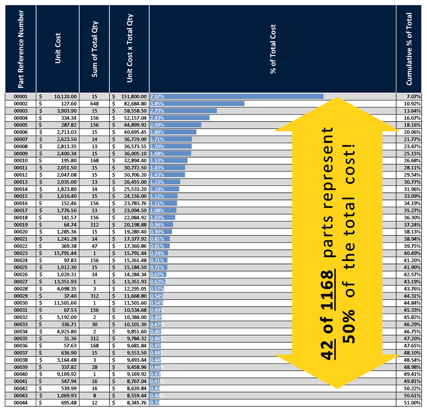
Depending on the project, savings of over 40% can be achieved, in my experience. The 1st key to this proposed method is to 1st generate a structured and costed bill of materials (BOM) to work from. When sorting the list by (Unit cost) x (quantity used) from largest to smallest, you may find that as little as 10% of the parts on top of the list make up between 50% to 80% of costs! It’s similar to the well-known 80/20 rule. This is all great news because now you can work on a small, targeted list to make a huge impact. To get the maximum savings, you'll also need to make a similar list of the sub-assemblies or sub-systems, sort them, and look for ways to eliminate parts altogether, or simplify by combining several parts into one integrated part, such as Sheetmetal, casting, molded, or 3D printed component. You can also make a list of functions and look for ways to combine or eliminate some functions. I’ve seen this work with industrial machinery consisting of hundreds or thousands of parts. What is your engineering team’s approach to using timing diagrams in machine development?
It is such a valuable tool from the conceptual stage to production that I'm surprised when I find that some machine builders are using them seldom or not at all. It is helpful to start the timing diagram in the conceptual phase, even before the actual 3D modeling starts, especially if many motions are involved. A chart makes it easy to find opportunities to overlap motions and reduce overall cycle time. Whether your motions are cam or servo driven, the diagram communicates what motions need to happen and how each device motion relates to the others. As the 3D model develops, the timing diagram should evolve in parallel. The diagram can be made in a 3D CAD environment, a sketch tool, spreadsheet, on paper, or with a 2D kinematics tool, as shown here, it's pretty simple and fast to keep it updated as changes are needed, and you may also include inertia, torque, and other dynamics calculations. The curves generated by most software tools can be exported and used to create physical cams or translated into parameters for servo motions for use in the control program. Later, as the machine begins testing and moves into production, it becomes a great way to consider what-if scenarios, train operators, troubleshoot problems, and consider future upgrades or modifications. |
AuthorRichard Lee is the owner of Lee Engineering Inc. and provides engineering and design services to manufacturers ArchivesCategories |


 RSS Feed
10/5/2022
3 Comments